


SJC
Steel-Joist Connectors
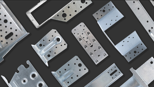
SJC connectors have been specifically designed for various CFS joist and rafter applications.
The unique clip dimensions enable easy installation on the open side of joists and rafters with up to 89mm flanges and return lips up to 19mm.

Product Details
Images

SJC - Joist to Girder Installation

SJC - Joist to RSJ Installation

SJC Header to Jam Installation

SJC10.25 Installation with Carried Member Fasteners in Inner Row

SJC8.25 Installation with Min. Screw Pattern (screw in round holes)
For max. screw pattern, fill all round and triangle holes.
Min./Max. patterns have screws only in outer row.
Features
Technical Data
Dimensions
.jpg")
SJC - Performance Values (Minimum Fasteners)

| References | Fasteners | Safe Working Loads (Min. Fasteners) [kN] | Characteristic Capacities (Min. Fasteners) [kN] | ||||||
|---|---|---|---|---|---|---|---|---|---|
| Pattern | Flange A | Flange B | R1=R2,SWL | R1=R2,k | |||||
| Qty | Type | Qty | Type | 1.6mm LGS | 2.0mm LGS | 1.6mm LGS | 2.0mm LGS | ||
| SJC10.25-R15 | Min | 4 | X1214D325 | 6 | X1214D325 | 5.2 | 7.2 | 8.3 | 11.6 |
SJC - Performance Values (Maximum Fasteners)
| References | Fasteners | Safe Working Loads (Maximum Fasteners) [kN] | Characteristic Capacities (Maximum Fasteners) [kN] | ||||||
|---|---|---|---|---|---|---|---|---|---|
| Pattern | Flange A | Flange B | R1 = R2,SWL | R1 = R2,k | |||||
| Qty | Type | Qty | Type | 1.6mm LGS | 2.0mm LGS | 1.6mm LGS | 2.0mm LGS | ||
| SJC10.25-R15 | Maximum | 7 | X1214D325 | 11 | X1214D325 | 5.6 | 9.1 | 9 | 14.6 |
SJC - Performance Values (Inner Fasteners)
| References | Fasteners | Safe Working Loads (Inner Fasteners) [kN] | Characteristic Capacities (Inner Fasteners) [kN] | ||||||
|---|---|---|---|---|---|---|---|---|---|
| Pattern | Flange A | Flange B | R1 = R2,SWL | R1 = R2,k | |||||
| Qty | Type | Qty | Type | 1.6mm LGS | 2.0mm LGS | 1.6mm LGS | 2.0mm LGS | ||
| SJC10.25-R15 | Inner | 5 | X1214D325 | 7 | X1214D325 | 7.7 | 11.7 | 12.3 | 18.8 |
Table Notes:
- Performance values are based upon tests completed by Simpson Strong-Tie U.S. in accordance to ICC-ES AC261 - Acceptance criteria for connectors used with Cold-Formed Steel Structural Members
- Minimum fastener quantity and load values — fill all round holes; Maximum fastener quantity and load values — fill all round and triangular holes; Inner fastener quantity and load values — see illustrations for fastener placement.
- When supporting member is a RSJ, fasteners in flange A should be X1224D540
- Loads are based on bracing of the members located within 300mm of the connection.
Installation
Installation
SJC - Joist to Girder Installation
SJC - Joist to RSJ Installation
SJC Header to Jam Installation
SJC8.25 Installation with Min. Screw Pattern (screw in round holes)
For max. screw pattern, fill all round and triangle holes.
Min./Max. patterns have screws only in outer row.

SJC8.25 Inner Fastener Pattern
SJC10.25 Installation with Carried Member Fasteners in Inner Row

SJC10.25 Inner Fastener Pattern

X1214D325 - Used for standard installation onto LGS Studs

X1224D540 - Used for installation on RSJ