


H/L
Heavy/Light Restraint Straps
The H and L straps are designed to The Building Regulations for
horizontal and vertical restraint.
- Heavy restraint straps meet requirements for lateral restraint of roof trusses, rafters and joists tied into masonry walls.
- Light restraint straps are designed for vertical loads such as wall plates on top of masonry walls.
- All common sizes in stock from 500 to 2000mm long, 50mm increments. Longer lengths avaialble to order; contact technical support.
CE Marking
EPD

Product Details
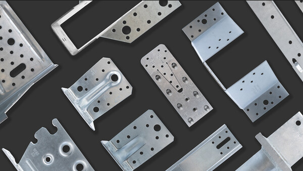
Images


Features

Flat Strap

Strap with a Bend

Strap with a double bend.

Strap with a twist

Strap with a bend and a twist
Technical Data
Dimensions

Installation
Installation

Installation - Floor (5)

Installation - Floor (4)

Installation - Floor (2)

Installation - Floor (3)


Installation - Floor (1)


