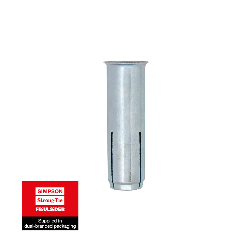
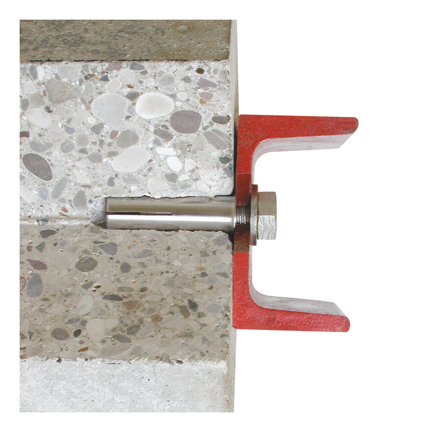
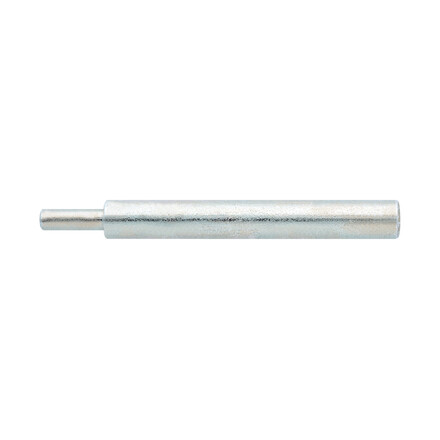
Rimmed Hammerset Anchor
Hammerset anchor with metric internal thread M6 - M16 for medium load range for anchoring in non-cracked concrete C20/25 - C50/60 and for multiple fixings of non-load bearing systems in concrete.
Product Details
Features
Material
- Steel
- White zinc plated
Benefits
- Safe and controlled expansion
- Fast application
- Shallow embedment depth
- Rimmed plug version for easy installation flush with base material
- High strength in relation to embedment depths
- Fire resistance R120
Application
Applications
- Suspended ceiling applications
- Pipework
- Sprinkler systems
Suitable for
- Multiple use for non-structural
- applications on cracked
- and non-cracked concrete
- Solid stone
Technical Data
Autres
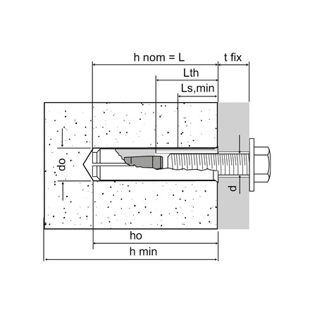
Product Dimension - Rimmed hammerset anchor
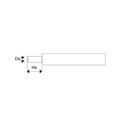
| References | Product Reference | Plug [Ø x L] | Dimensions [dxL] [mm] | Hole diameter [do] [mm] | Cylindrical hole depth [h0] [mm] | Nominal embedment depth [hnom] [mm] | Threaded length [Lth] [mm] | Max. thread engagement [Ls,min] [mm] | Torque [Tinst] [Nm] | Qty per box | Qty per outer box |
|---|---|---|---|---|---|---|---|---|---|---|---|
| 75205B0600000 | TAP | 8x25* | M6x25 | 8 | 25 | 25 | 11 | 6 | 4 | 100 | 2000 |
| 75205B0800000 | 10x30 | M8x30 | 10 | 30 | 30 | 13 | 8 | 8 | 100 | 1000 | |
| 75205B1003000 | 12x30* | M10x30 | 12 | 30 | 30 | 12 | 10 | 15 | 100 | 600 | |
| 75205B1000000 | 12x40 | M10x40 | 12 | 40 | 40 | 17 | 10 | 15 | 100 | 600 | |
| 75205B1200000 | 15x50 | M12x50 | 15 | 50 | 50 | 21 | 12 | 35 | 50 | 300 | |
| 75205B1600000 | 20x65** | M16x65 | 20 | 65 | 65 | 30 | 16 | 60 | 25 | 150 |
* Only ETA 18/0433 ETAG 001 p.6 Multiple use
** Only ETA 18/0432 EAD-330232-00-0601 opt.7
Screw Length: Minimum: Ls,min + tfix - Maximum: Lth + tfix
Recommended loads / for single anchors / with no edge distances or spacings
| References | Design capacity | ||||||||
|---|---|---|---|---|---|---|---|---|---|
| Tension - Nrec | Shear - Vrec | Bending moment - MRd [Nm] | |||||||
| Non-cracked concrete C20/25 [kN] | Hollow concrete block [kN] | Hollow brick [kN] | Solid brick (BP400) [kN] | Non-cracked concrete C20/25 [kN] | Hollow concrete block [kN] | Hollow brick [kN] | Solid brick (BP400) [kN] | ||
| 75205B0600000 | - | - | - | - | - | - | - | - | - |
| 75205B0800000 | - | - | - | - | - | - | - | - | 8.98 |
| 75205B1003000 | - | - | - | - | - | - | - | - | 17.9 |
| 75205B1000000 | - | - | - | - | - | - | - | - | 17.9 |
| 75205B1200000 | - | - | - | - | - | - | - | - | 31.37 |
| 75205B1600000 | - | - | - | - | - | - | - | - | 79.82 |
1. The recommended loads have been calculated using the partial safety factors for resistances stated in ETA-approval(s) and with a partial safety factor for actions of γF=1.4. The loading figures
are valid for unreinforced concrete and reinforced concrete with a rebar spacing s ≥ 15 cm (any diameter) or with a rebar spacing s ≥ 10 cm, if the rebar diameter is 10 mm or smaller.
2. The figures for shear are based on a single anchor without influence of concrete edges. For anchorages close to edges (c ≤ max [10 hef; 60d]) the concrete edge failure shall be checked per
ETAG 001, Annex C, design method A.
3. Concrete is considered non-cracked when the tensile stress within the concrete is\sigmaL +\sigmaR ≤ 0. In the absence of detailed verification\sigmaR = 3 N/mm² can be assumed (\sigmaL equals the tensile
stress within the concrete induced by external loads, anchors loads included).
Design capacities - single anchor - no edge distances - ETA-18/0432
| References | Recommented loads - Non-cracked concrete (3) | |||||||||
|---|---|---|---|---|---|---|---|---|---|---|
| Dimensions [dxL] [mm] | Tension - Nrec(1) | Shear - Vrec (1-2) | Bending moment Mrec [Nm] | |||||||
| C20/25 [kN] | C30/37 [kN] | C40/50 [kN] | C50/60 [kN] | C20/25 [kN] | C30/37 [kN] | C40/50 [kN] | C50/60 [kN] | |||
| 75205B0600000 | M6x25 | - | - | - | - | - | - | - | - | - |
| 75205B0800000 | M8x30 | 3.3 | 4 | 4.7 | 5.1 | 4 | 4.9 | 5.6 | 6.2 | 8.98 |
| 75205B1003000 | M10x30 | - | - | - | - | - | - | - | - | - |
| 75205B1000000 | M10x40 | 5.1 | 6.2 | 7.2 | 7.9 | 6.1 | 7.4 | 8.6 | 9.5 | 17.9 |
| 75205B1200000 | M12x50 | 6.1 | 7.4 | 8.6 | 9.5 | 8.5 | 10.4 | 12 | 13.2 | 17.9 |
| 75205B1600000 | M16x65 | 9.9 | 12.1 | 14 | 15.3 | 25.2 | 30.7 | 35.6 | 35.9 | 31.37 |
1. The design loads loads have been calculated using the partial safety factors for resistances stated in ETA-approval(s). The loading figures are valid for unreinforced concrete and reinforced concrete with a rebar spacing s ≥ 15 cm (any diameter) or with a rebar spacing s ≥ 10 cm, if the rebar diameter is 10mm or smaller.
2. The figures for shear are based on a single anchor without influence of concrete edges. For anchorages close to edges (c ≤ max [10 hef; 60d]) the concrete edge failure shall be checked per ETAG 001, Annex C, design method A.
3. Concrete is considered non-cracked when the tensile stress within the concrete is\sigmaL +\sigmaR ≤ 0. In the absence of detailed verification\sigmaR = 3 N/mm² can be assumed (\sigmaL equals the tensile stress within the concrete induced by external loads, anchors loads included).
*Not covered by ETA-18/0432
Recommended capacities - single anchor - no edge distances
| References | Design capacity | ||||||||
|---|---|---|---|---|---|---|---|---|---|
| Tension - Nrec | Shear - Vrec | Bending moment - MRd [Nm] | |||||||
| Non-cracked concrete C20/25 [kN] | Hollow concrete block [kN] | Hollow brick [kN] | Solid brick (BP400) [kN] | Non-cracked concrete C20/25 [kN] | Hollow concrete block [kN] | Hollow brick [kN] | Solid brick (BP400) [kN] | ||
| 75205B0600000 | - | - | - | - | - | - | - | - | - |
| 75205B0800000 | - | - | - | - | - | - | - | - | 8.98 |
| 75205B1003000 | - | - | - | - | - | - | - | - | 17.9 |
| 75205B1000000 | - | - | - | - | - | - | - | - | 17.9 |
| 75205B1200000 | - | - | - | - | - | - | - | - | 31.37 |
| 75205B1600000 | - | - | - | - | - | - | - | - | 79.82 |
1. The recommended loads have been calculated using the partial safety factors for resistances stated in ETA-approval(s) and with a partial safety factor for actions of γF=1.4. The loading figures
are valid for unreinforced concrete and reinforced concrete with a rebar spacing s ≥ 15 cm (any diameter) or with a rebar spacing s ≥ 10 cm, if the rebar diameter is 10 mm or smaller.
2. The figures for shear are based on a single anchor without influence of concrete edges. For anchorages close to edges (c ≤ max [10 hef; 60d]) the concrete edge failure shall be checked per
ETAG 001, Annex C, design method A.
3. Concrete is considered non-cracked when the tensile stress within the concrete is\sigmaL +\sigmaR ≤ 0. In the absence of detailed verification\sigmaR = 3 N/mm² can be assumed (\sigmaL equals the tensile stress within the concrete induced by external loads, anchors loads included).
Recommended capacities - multiple use cracked and un-cracked concrete ETA-18/0433
| References | Product Reference | Dimensions [dxL] [mm] | cracked and uncracked concrete |
|---|---|---|---|
| tension / shear load Rrec [kN] | |||
| 75205B0600000 | TAP | M6x25 | 0.5 |
| 75205B0800000 | TAP | M8x30 | 0.7 |
| 75205B1003000 | TAP | M10x30 | - |
| 75205B1000000 | TAP | M10x40 | 1 |
| 75205B1200000 | TAP | M12x50 | 1.4 |
| 75205B1600000 | TAP | M16x65 | - |
The design loads FRD derive from the characteristic loads on the ETA certification and are inclusive of the partial safety factors γM
The recommended loads F derive from the characteristic loads on the ETA certification and are inclusive of the partial safety factors γF=1.4 and γM
Installation
Installation
Installation data
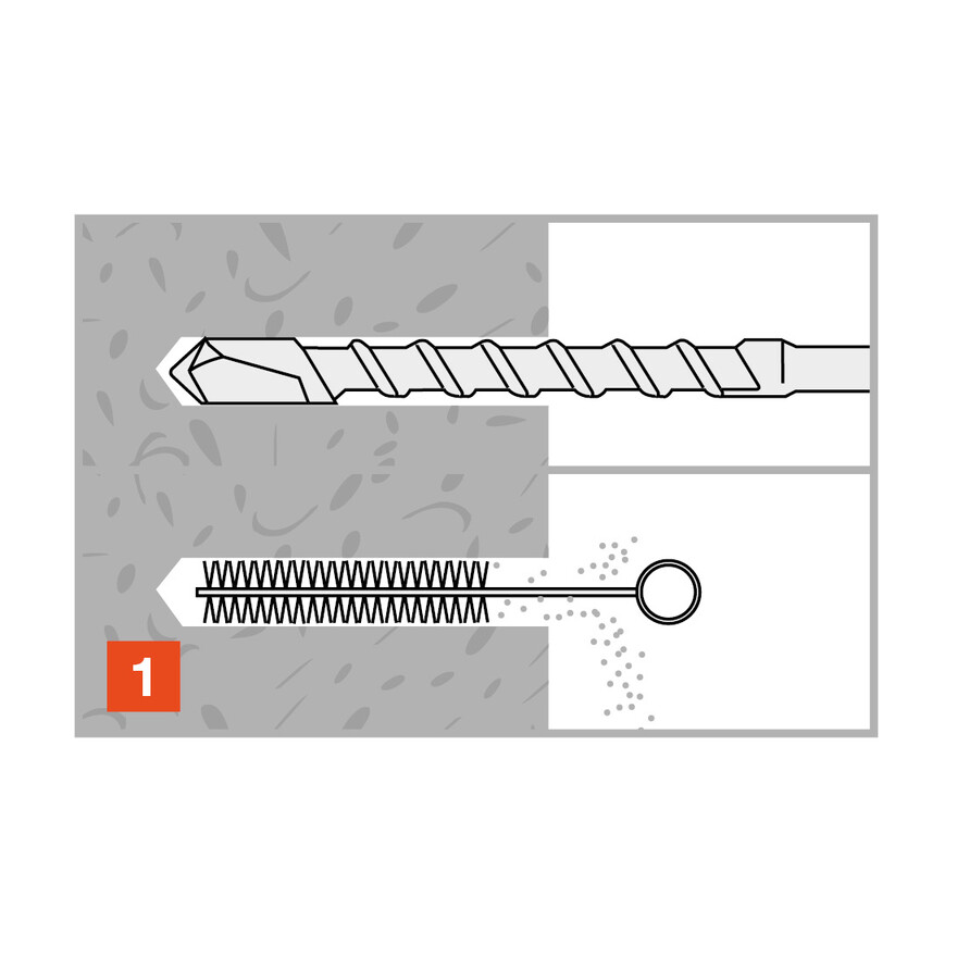
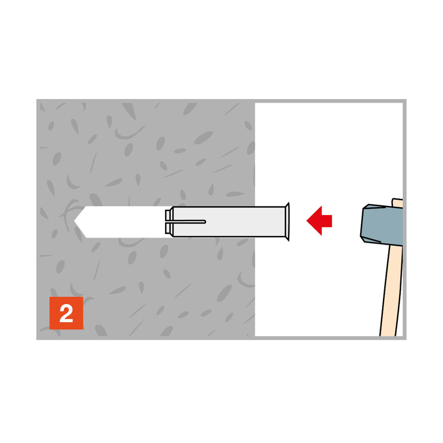
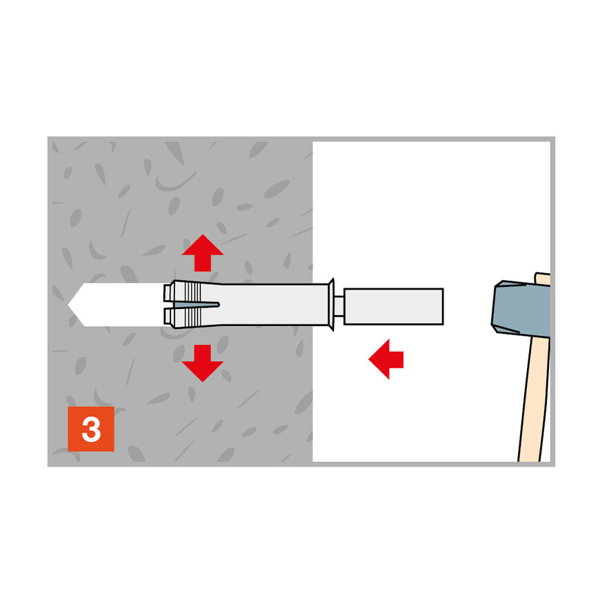
| References | Product Reference | Dimensions [dxL] [mm] | Ø drilling hole [d0] [mm] | Min. drill depth [h1] [mm] | Ø drilling fixture [df] [mm] | Wrench size [SW] [mm] | Installation torque [Tinst] [Nm] | Embedment depth [hef] [mm] | Min. support thickness [hmin] [mm] |
|---|---|---|---|---|---|---|---|---|---|
| 75205B0600000 | TAP | M6x25 | 8 | 25 | 7 | - | 4 | 25 | - |
| 75205B0800000 | TAP | M8x30 | 10 | 30 | 9 | - | 8 | 30 | 100 |
| 75205B1003000 | TAP | M10x30 | 12 | 40 | 12 | - | 15 | 40 | 100 |
| 75205B1000000 | TAP | M10x40 | 12 | 40 | 12 | - | 15 | 40 | 100 |
| 75205B1200000 | TAP | M12x50 | 15 | 50 | 14 | - | 35 | 50 | 100 |
| 75205B1600000 | TAP | M16x65 | 20 | 65 | 18 | - | 60 | 65 | 130 |
Spacing and edge distances - ETA-18/0432
| References | Product Reference | Dimensions [dxL] [mm] | Min. edge distance [cmin] [mm] | Min. spacing [smin] [mm] | Characteristic edge distance [ccr,N] [mm] | Characteristic spacing(5) - Scr,N [scr,N] [mm] |
|---|---|---|---|---|---|---|
| 75205B0600000 | TAP | M6x25 | - | - | - | - |
| 75205B0800000 | TAP | M8x30 | 41 | 41 | 45 | 90 |
| 75205B1003000 | TAP | M10x30 | 54 | 54 | 60 | 120 |
| 75205B1000000 | TAP | M10x40 | 54 | 54 | 60 | 120 |
| 75205B1200000 | TAP | M12x50 | 68 | 68 | 75 | 150 |
| 75205B1600000 | TAP | M16x65 | 88 | 88 | 97 | 195 |
* Not included in the approval
Spacing and edge distance ETA-18-0433
| References | Product Reference | Dimensions [dxL] [mm] | Embedment depth hef [mm] | Min. support thickness hmin [mm] | Min. edge distance [cmin] [mm] | Min. spacing [smin] [mm] |
|---|---|---|---|---|---|---|
| 75205B0600000 | TAP | M6x25 | 25 | 80 | 200 | 150 |
| 75205B0800000 | TAP | M8x30 | 30 | 80 | 200 | 150 |
| 75205B1003000 | TAP | M10x30 | - | - | - | - |
| 75205B1000000 | TAP | M10x40 | 40 | 80 | 200 | 150 |
| 75205B1200000 | TAP | M12x50 | 50 | 100 | 200 | 150 |
| 75205B1600000 | TAP | M16x65 | - | - | - | - |
