


FM-753 CRACK A4

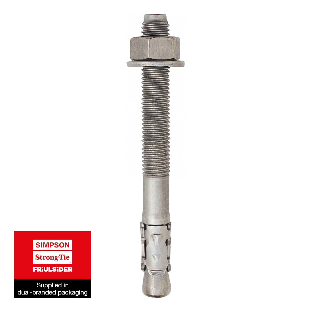
Stainless Steel Heavy Duty Wedge Anchor with Seismic Certification

Stainless steel wedge anchor for the medium load range in sizes M8 - M16 for anchoring in cracked and non-cracked concrete C20/25 - C50/60, as well as for seismic actions of the performance category C1/C2.

CE Marking

ETA
Stainless steel A4
Fire resistance R 120

Seismic C1 C2

Fix Calc
Product Details

Images
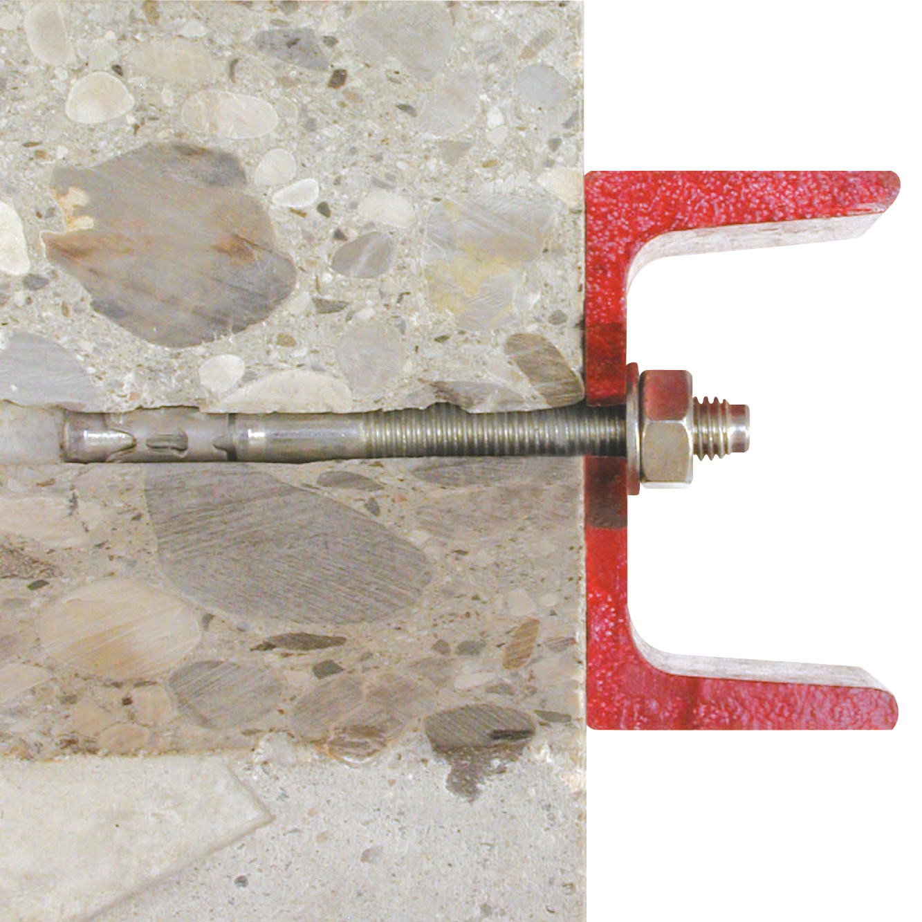
Features

Material

  • Stainless steel A4

Benefits

  • Dynamic and seismic loads
  • Seismic performance C1 and C2
  • Immediate expansion
  • Increased thickness of three expander segments
  • Nine gripping dents for greater adhesion to hole wall
  • Fire resistance R120

Application

Applications

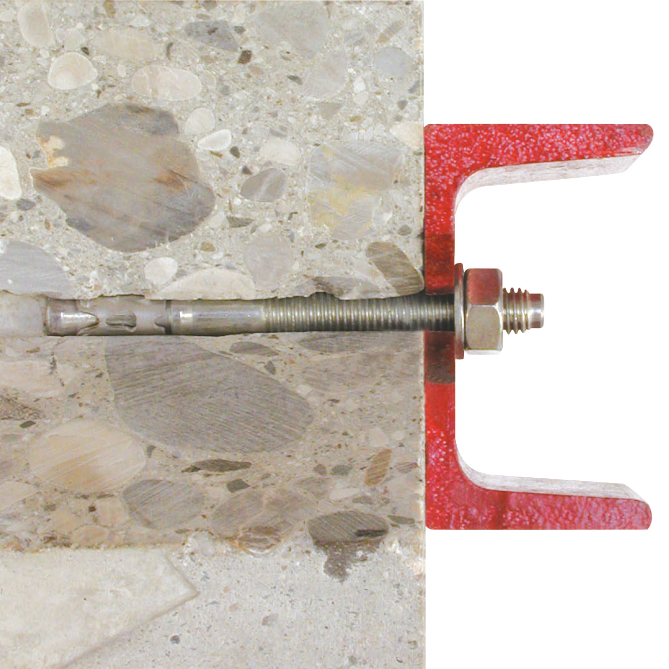
  • Structural fixings
  • Steel constructions
  • Seismic applications

Suitable for

  • Cracked concrete
  • Non-cracked concrete
  • Solid stone

Technical Data

Dimensions

Autres

Product dimensions

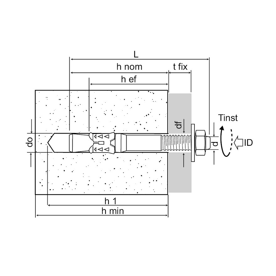
References Product Reference Dimensions [mm] Thread length Fixture thickness [tfix,max] with standard setting depth [hef,STD] [mm] Fixture thickness [tfix,max] with reduced setting depth [hef,RED] [mm] Hole diameter in fixture [df] [mm] Hole diameter [do] x depth [h1] in substrate with standard setting depth [hef,STD] [mm] Hole diameter [do] x depth [h1] in substrate with reduced setting depth [hef,RED] [mm] Min. setting depth [hef,STD] [mm] Reduced setting depth [hef,RED]  [mm] Qty per box Qty per outer box Weight [kg]
7535000806800FM-753 CRACK A4M8x683041898x708x5648341004000.03
7535000807500FM-753 CRACK A4M8x7530102498x708x5648341004000.032
7535001009000FM-753 CRACK A4M10x904010301210x8010x606040502000.058
7535001211000FM-753 CRACK A4M12x1106510301412x10012x807252502000.1
7535001212000FM-753 CRACK A4M12x1206520401412x10012x807252502000.11
7535001214500FM-753 CRACK A4M12x1458545651412x10012x807252251000.13

Recommended loads / Non-cracked concrete / for single anchors / with no edge distances or spacings

References Product Reference Dimensions [mm] Recommended loads - Non-cracked concrete
Tension - Nrec Shear - Vrec Bending moment Mrec [Nm]
C20/25 [kN] C30/37 [kN] C40/50 [kN] C50/60 [kN] C20/25 [kN] C30/37 [kN] C40/50 [kN] C50/60 [kN]
7535000806800FM-753 CRACK A4M8x684.85.96.87.47.87.87.87.810.5
7535000807500FM-753 CRACK A4M8x754.85.96.87.47.87.87.87.810.5
7535001009000FM-753 CRACK A4M10x907.69.310.711.813.413.413.413.421.5
7535001211000FM-753 CRACK A4M12x11010.512.814.816.317.317.317.317.337.4
7535001212000FM-753 CRACK A4M12x12010.512.814.816.317.317.317.317.337.4
7535001214500FM-753 CRACK A4M12x14510.512.814.816.317.317.317.317.337.4

1) In case of interaction of tension and shear loads (lever arm) as well as in case of anchor groups and/or edge influence, a design according to EN 1992-4 (seismic actions - Annex C / fire action
- Annex D) shall be carried out taking into account the entire European Technical Assessment ETA-10/0293.
2) The load data take into account the partial safety factors of the resistances given in the European Technical Assessment (ETA) and a partial safety factor of the actions
of γF = 1.4. The values given assume unreinforced or normally reinforced concrete with a spacing of the reinforcing bars s ≥ 15 cm or s ≥ 10 cm at a
rebar diameter ds ≤ 10 mm is assumed.   

Design capacities - single anchor - no edge distances - Uncracked concrete

References Product Reference Dimensions [mm] Design capacity - Non-cracked concrete (3)
Tension - NRd (1) Shear - VRd (1-2) Bending moment MRd [Nm]
C20/25 [kN] C30/37 [kN] C40/50 [kN] C50/60 [kN] C20/25 [kN] C30/37 [kN] C40/50 [kN] C50/60 [kN]
7535000806800FM-753 CRACK A4M8x686.7---10.9----
7535000807500FM-753 CRACK A4M8x756.7---10.9----
7535001009000FM-753 CRACK A4M10x9010.7---18.8----
7535001211000FM-753 CRACK A4M12x11014.7---24.2----
7535001212000FM-753 CRACK A4M12x12014.7---24.2----
7535001214500FM-753 CRACK A4M12x14514.7---24.2----

1. The design loads loads have been calculated using the partial safety factors for resistances stated in ETA-approval(s). The loading figures are valid for unreinforced concrete and reinforced concrete with a rebar spacing s ≥ 15 cm (any diameter) or with a rebar spacing s ≥ 10 cm, if the rebar diameter is 10mm or smaller.
2. The figures for shear are based on a single anchor without influence of concrete edges. For anchorages close to edges (c ≤ max [10 hef; 60d]) the concrete edge failure shall be checked per ETAG 001, Annex C, design method A.
3. Concrete is considered non-cracked when the tensile stress within the concrete is\sigmaL +\sigmaR ≤ 0. In the absence of detailed verification\sigmaR = 3 N/mm² can be assumed (\sigmaL equals the tensile stress within the concrete induced by external loads, anchors loads included).

Recommended loads - Cracked concrete - single anchor - no edge distances

References Product Reference Dimensions [mm] Recommended loads - Cracked concrete
Tension - Nrec Shear - Vrec Bending moment Mrec [Nm]
C20/25 [kN] C30/37 [kN] C40/50 [kN] C50/60 [kN] C20/25 [kN] C30/37 [kN] C40/50 [kN] C50/60 [kN]
7535000806800FM-753 CRACK A4M8x683.13.84.44.85.45.45.45.410.5
7535000807500FM-753 CRACK A4M8x753.13.84.44.85.45.45.45.410.5
7535001009000FM-753 CRACK A4M10x904.85.96.87.413.413.413.413.421.5
7535001211000FM-753 CRACK A4M12x1106.27.68.79.617.317.317.317.337.4
7535001212000FM-753 CRACK A4M12x1206.27.68.79.617.317.317.317.337.4
7535001214500FM-753 CRACK A4M12x1456.27.68.79.617.317.317.317.337.4

1) In case of interaction of tension and shear loads (lever arm) as well as in case of anchor groups and/or edge influence, a design according to EN 1992-4 (seismic actions - Annex C / fire action
- Annex D) shall be carried out taking into account the entire European Technical Assessment ETA-10/0293.
2) The load data take into account the partial safety factors of the resistances given in the European Technical Assessment (ETA) and a partial safety factor of the actions
of γF = 1.4. The values given assume unreinforced or normally reinforced concrete with a spacing of the reinforcing bars s ≥ 15 cm or s ≥ 10 cm at a
rebar diameter ds ≤ 10 mm is assumed.   

Design capacities - single anchor - no edge distances - Cracked concrete

References Product Reference Dimensions [mm] Design capacities - single anchor - no edge distances
Design capacity - Cracked concrete (3)
Tension - NRd(1) Shear - VRd(1-2) Bending moment MRd [Nm]
C20/25 [kN] C30/37 [kN] C40/50 [kN] C50/60 [kN] C20/25 [kN] C30/37 [kN] C40/50 [kN] C50/60 [kN]
7535000806800FM-753 CRACK A4M8x684.3---7.6----
7535000807500FM-753 CRACK A4M8x754.3---7.6----
7535001009000FM-753 CRACK A4M10x906.7---18.8----
7535001211000FM-753 CRACK A4M12x1108.7---24.2----
7535001212000FM-753 CRACK A4M12x1208.7---24.2----
7535001214500FM-753 CRACK A4M12x1458.7---24.2----

1. The design loads loads have been calculated using the partial safety factors for resistances stated in ETA-approval(s). The loading figures are valid for unreinforced concrete and reinforced concrete with a rebar spacing s ≥ 15 cm (any diameter) or with a rebar spacing s ≥ 10 cm, if the rebar diameter is 10mm or smaller.
2. The figures for shear are based on a single anchor without influence of concrete edges. For anchorages close to edges (c ≤ max [10 hef; 60d]) the concrete edge failure shall be checked per ETAG 001, Annex C, design method A.
3. Concrete is considered non-cracked when the tensile stress within the concrete is\sigmaL +\sigmaR ≤ 0. In the absence of detailed verification\sigmaR = 3 N/mm² can be assumed (\sigmaL equals the tensile stress within the concrete induced by external loads, anchors loads included).

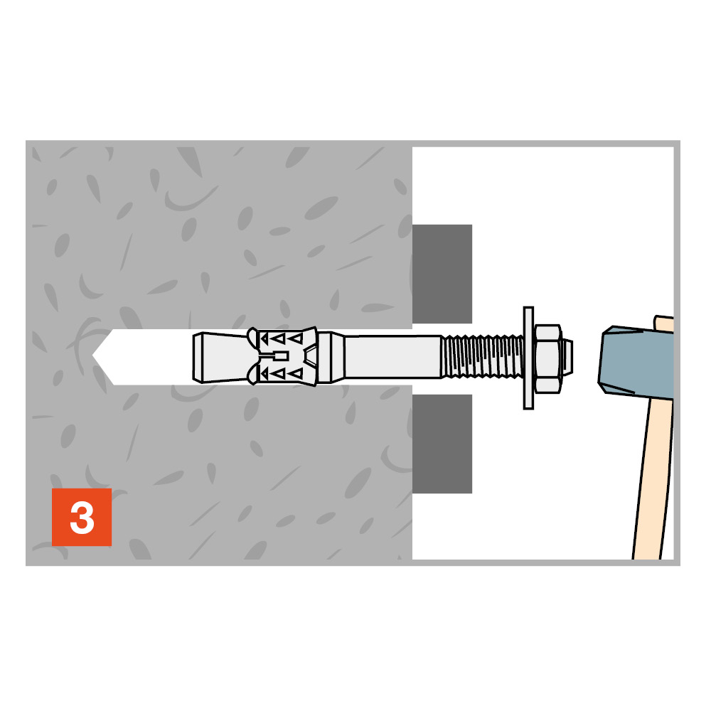
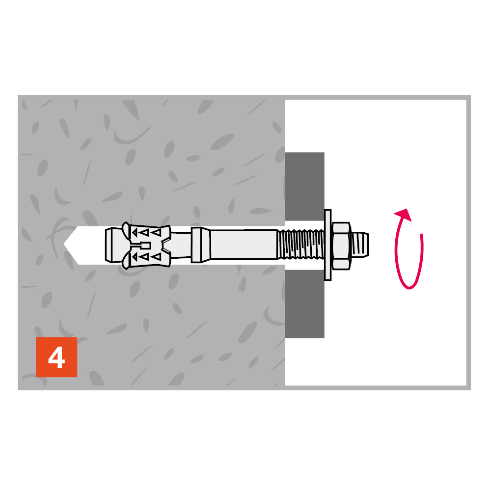
Installation

Installation

Installation data

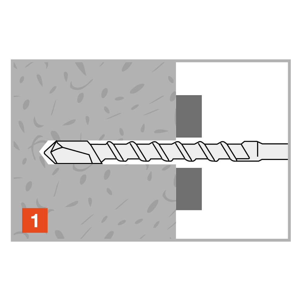
References Product Reference Dimensions [mm] Ø drilling hole [d0] [mm] Min. drill depth [h1] [mm] Ø drilling fixture [df] [mm] Wrench size [SW] [mm] Installation torque [Tinst] [Nm] Embedment depth [hef] [mm] Min. support thickness [hmin] [mm]
7535000806800FM-753 CRACK A4M8x688709132048100
7535000807500FM-753 CRACK A4M8x758709132048100
7535001009000FM-753 CRACK A4M10x90108012174060120
7535001211000FM-753 CRACK A4M12x1101210014196072150
7535001212000FM-753 CRACK A4M12x1201210014196072150
7535001214500FM-753 CRACK A4M12x1451210014196072150

Spacings and edge distances

References Product Reference Dimensions [mm] Min. edge distance [cmin] [mm] Min. spacing [smin] [mm] Characteristic edge distance [ccr,N] [mm] Characteristic spacing(5) - Scr,N [scr,N] [mm]
7535000806800FM-753 CRACK A4M8x68505072144
7535000807500FM-753 CRACK A4M8x75505072144
7535001009000FM-753 CRACK A4M10x90505590180
7535001211000FM-753 CRACK A4M12x1106060108216
7535001212000FM-753 CRACK A4M12x1206060108216
7535001214500FM-753 CRACK A4M12x1456060108216

Certification

Declaration of Performance (DoP)

European Technical Assessment (ETA)

ZIP Packages

Buy from Distributor

No items available.

Contact

Simpson Strong-Tie U.K.

Simpson Strong-Tie

Cardinal Point, Winchester Road
Tamworth
Staffordshire
B78 3HG
United Kingdom