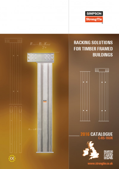
Steel Strong-Wall for Timber Frame Racking Resistance.
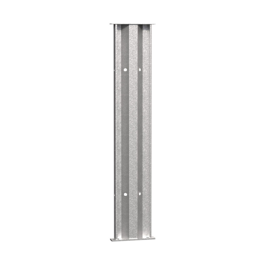
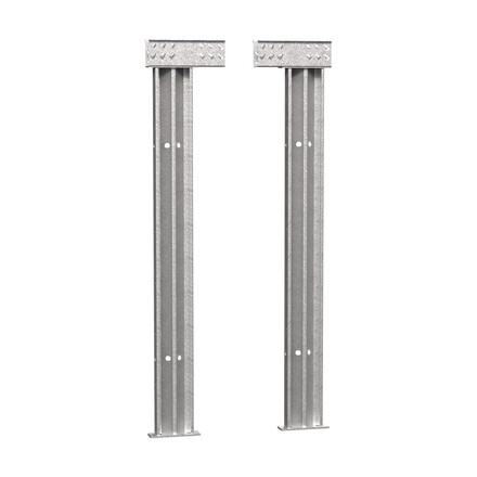
The Steel Strong-Wall is a corrugated steel panel which is designed to be fixed directly to the concrete foundations of a building, within the external or internal wall, via a bolted connection.
Being relatively small in width the Steel Strong-Wall™ can be used
in areas where only small sections of wall are available, offering
significantly higher racking resistance than the equivalent sized
standard timber frame wall panel.
Product Details
Images
Features
Material
- Steel Strong-Wall: Galvanised mild steel - Z275.
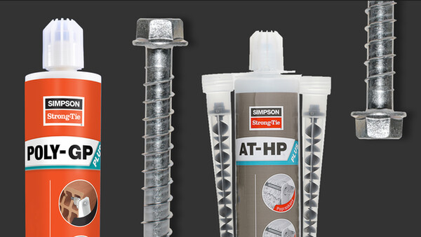
- AT-HP adhesive: Strene free, methacylate resin.
- Threaded Rods: Grade 8.8 carbon steel, zinc plated.
- Nuts and washers: Carbojn steel, zinc plated.
- Screws: SDS25112.
Benefits
- Available in three widths: 300mm, 450mm and 600mm.
- Available height ranges: 1900mm to 2700mm.
- At only 89mm wide, it can be fitted into standard 89mm and 140mm deep timber frame panels.
- All fixings and adhesives required for installation are included.
Application
Applications
- The Steel Strong-Wall can be used in conjunction with either 89mm or 140mm deep stud walls (and any thickness in between).
- Around openings such as garages, patio doors and bay windows.
- Narrow piers
- Internal walls
- External walls
Technical Data
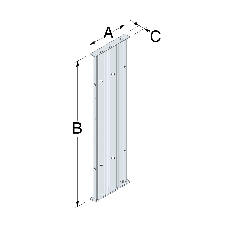
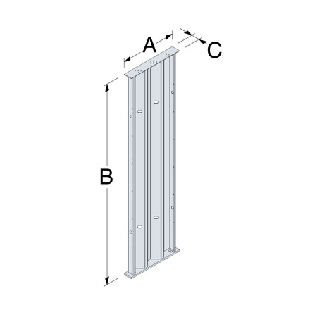
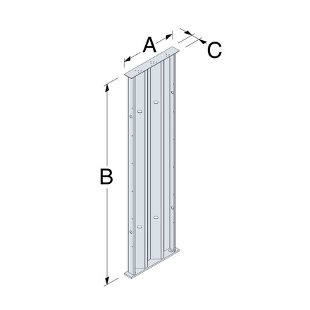
Product Range & Performance Values For BS Design Methods (Height (B) Range 1900mm - 2200mm)
| References | Dimensions and drill holes [mm] | Ancrages | Fasteners to Top Rail | Permissible loads [kN] | Anchor Loads at Racking Loads [kN] | ||||||
|---|---|---|---|---|---|---|---|---|---|---|---|
| Width | Height | Depth | Qty | Specification | Qty | Specification | Racking Rb | Axial | Tension | Shear | |
| SSW300 | 300 | 1900 - 2200 | 89 | 2 | M20 x 210 | 4 | Ø6.35 x 89 | 1.75 | 15 | T = 7.697 x Rb | F/2 |
| SSW450 | 450 | 1900 - 2200 | 89 | 2 | M24 x 210 | 10 | Ø6.35 x 89 | 6 | 22.5 | T = 5.297 x Rb | F/2 |
| SSW600 | 600 | 1900 - 2200 | 89 | 2 | M24 x 210 | 14 | Ø6.35 x 89 | 10.5 | 30 | T = 2.812 x Rb | F/2 |
Product Range & Performance Values For BS Design Methods (Height (B) Range 2201mm - 2700mm)
| References | Dimensions and drill holes [mm] | Ancrages | Fasteners to Top Rail | Permissible loads [kN] | Anchor Loads at Racking Loads [kN] | ||||||
|---|---|---|---|---|---|---|---|---|---|---|---|
| Width | Height | Depth | Qty | Specification | Qty | Specification | Racking Rb | Axial | Tension | Shear | |
| SSW300 | 300 | 2201 - 2700 | 89 | 2 | M20 x 210 | 4 | Ø6.35 x 89 | 1.5 | 15 | T = 5.360 x Rb | F/2 |
| SSW450 | 450 | 2201 - 2700 | 89 | 2 | M24 x 210 | 10 | Ø6.35 x 89 | 5.5 | 22.5 | T = 2.704 x Rb | F/2 |
| SSW600 | 600 | 2201 - 2700 | 89 | 2 | M24 x 210 | 14 | Ø6.35 x 89 | 9.5 | 30 | T = 3.722 x Rb | F/2 |
Table Notes:
- Fasteners are supplied with Steel Strong-Wall panel - Reference SDS25312.
- Rb is the test racking resistance determined from tests carried out in accordance to BS EN 594:2011
- It is the responsibility of the building engineer/designer to ensure the foundation and hold down anchors can take the applied Tension and Compression loads.
- F refers to applied racking load
- Axial loads have been determined with corresponding maximum racking load
Installation
Installation
General Information
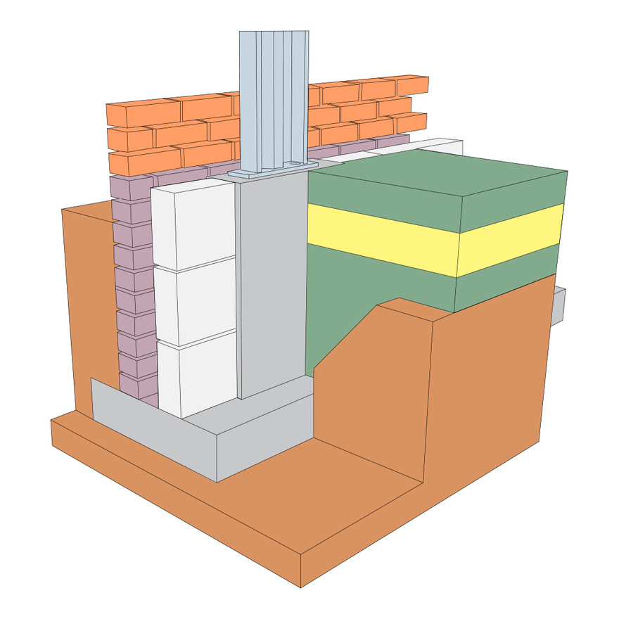
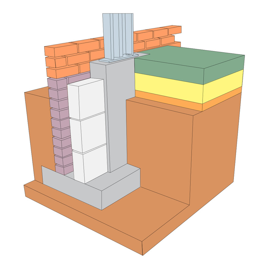
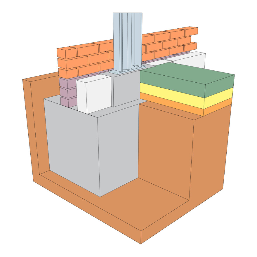
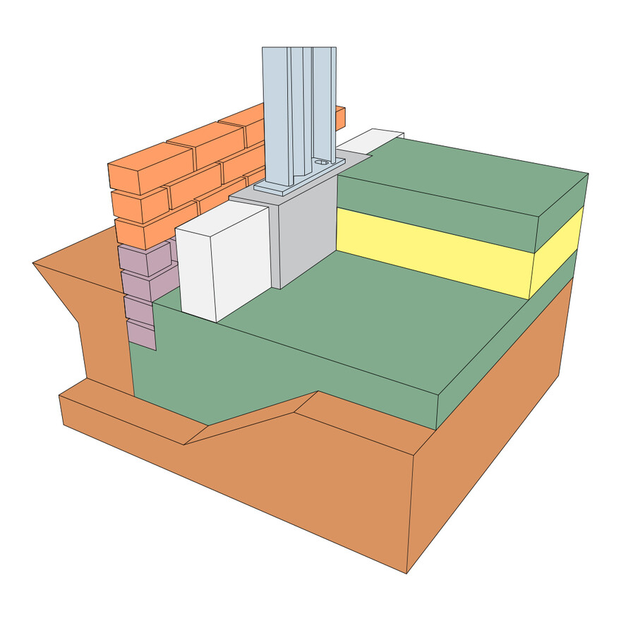
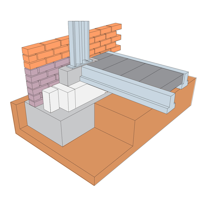
- The Steel-Strong-Wall should be fixed directly to the concrete foundation.
- DO NOT sit the Steel Strong-Wall on a timber sole plate.
- A DPC is required between the Steel Strong-Wall™ panel and the concrete foundation.
- The concrete foundation should be designed by the engineer repsonsible for the structure to accommodate
- the hold down anchors and resist the applied loads.
Equipment Required
1 off 24mm (SSW300) or 28mm (SSW450/SSW600) masonry drill, min. 300mm long.
1 off Dust Brush (item code BR17/30).*
1 off Dust Pump (item code PUMP).*
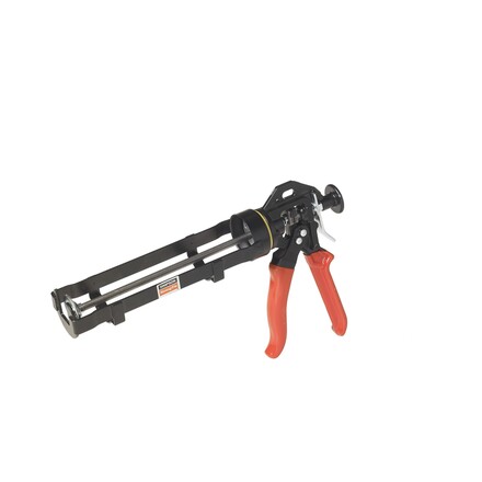
1 off Resin Dispensing Gun (item code DT380).*
1 off 30mm (SSW300) or 36mm (SSW450/SSW600) A/F, Long Length Socket
1 off Torque Wrench (min. capacity 150Nm (SSW300) or 200Nm (SSW450/SSW600).
1 off SDS 1/4 Hex Drive (SDSD3/8-RB).*
* Available from Simpson Strong-Tie, call 01827 255600 for prices.
Installation
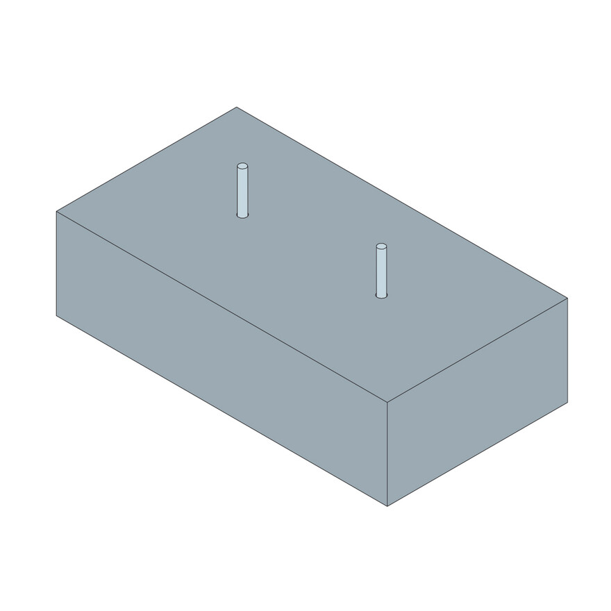
1a - Position the Steel Strong-Wall on top of the foundations in the required position, ensuring the correct orientation of the wall, with the fixing holes facing internally. Mark the foundation through the holes.
1b - Drill vertical holes to the stated diameter and depth:
SSW300 = Ø22mm x 160mm
SSW450 & SSW600 = Ø28mm x 160mm
1c - Ensure the holes are cleaned thoroughly.
1d - Install the anchor bolts supplied: AT-HP resin with M20 X 210 threaded rod for SSW300 and M24 X 210 threaded rod for SSW450 and SSW600.
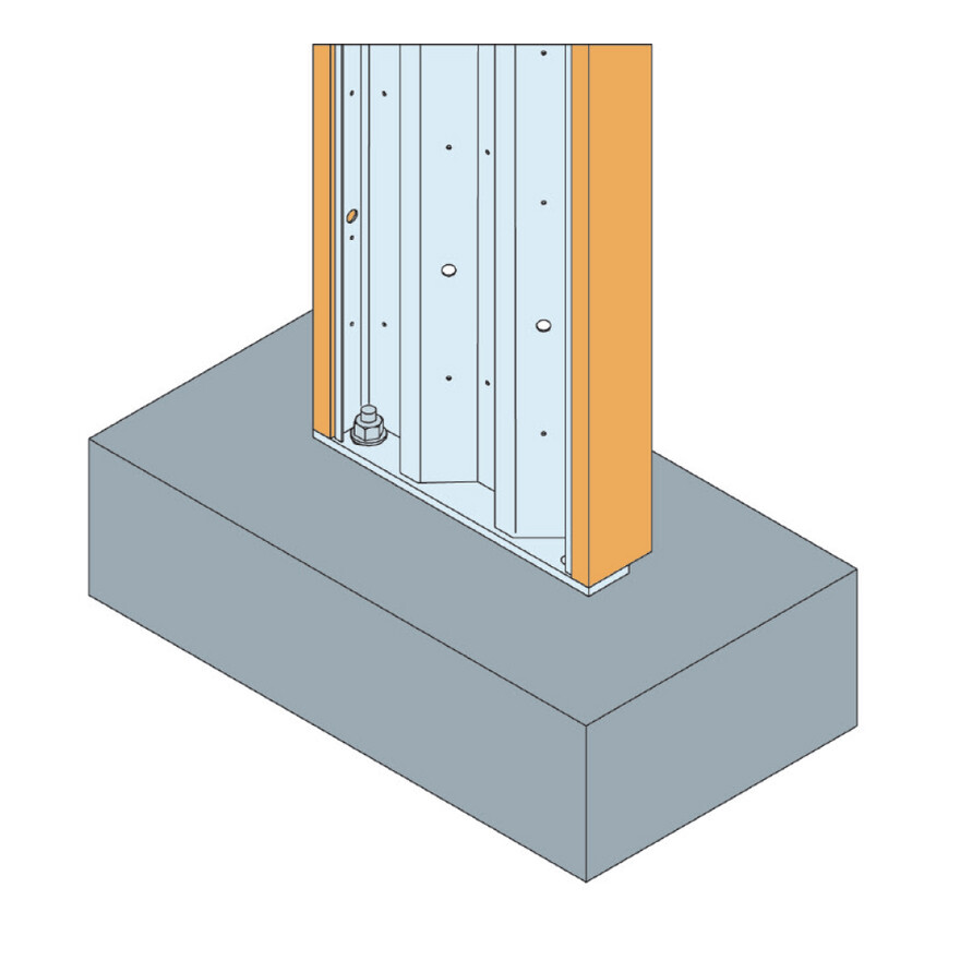
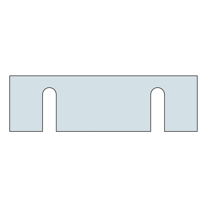
2a - Position the Steel Strong-Wall™ over the anchor bolt rods and level by using steel shims and structural grout if required. Plumb and where necessary, provide temporary bracing, which can be adjacent timber frame panels if already installed.
2b - Install nuts and washers and tighten by hand. Once the AT-HP
resin has cured (see cartridge label for cure times) tighten the nut to the recommended torque (M20: 150 Nm torque, using torque wrench with a 30mm socket. M24: 200 Nm torque, 36mm socket). Do not over-tighten nuts as this may lead to premature failure.
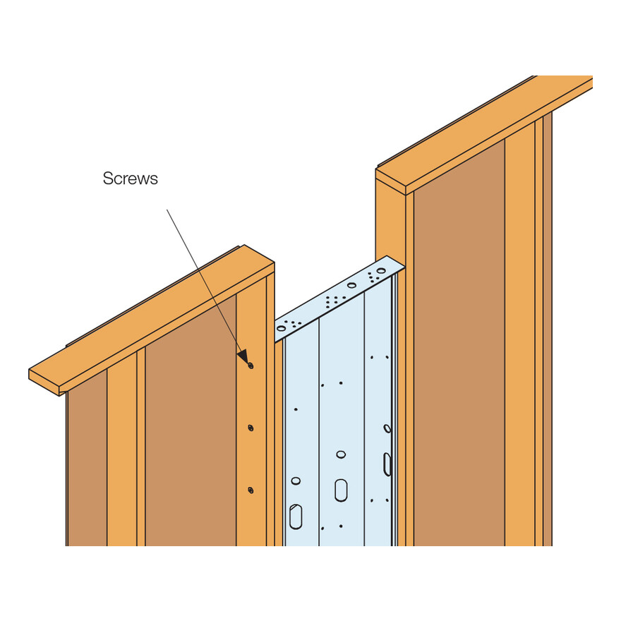
2c - Attach vertical timber studs to both sides of the Steel Strong-Wall using the short SDS screws provided.
Note: Where necessary to aid levelling of the wall, steel shims are available to order in widths 300, 450 and 600mm and thicknesses 1, 2 and 3.5mm. Contact Simpson Strong-Tie for details.
3a - The Steel Strong-Wall™ can be secured to the adjacent timber frame wall panels using SDW22300 screws (not supplied), installed from the timber frame side as shown in fig. 3a. the spacing of the SDW screws is to be determined by the engineer responsible for the design structure.
Lateral Capacity of SDW22300 Screw:
BS 5268: 0.9kN (short term) Based on 38mm thick C16 timber frame and 38mm thick Steel Strong-Wall stud. Alternate fastening specification shall be in accordance to engineers instructions.
4a - Connect the top of the Steel Strong-Wall™ to the timber frame structure through the pre-drilled holes in the top plate with the long SDS screws provided. If required, as a height makeup piece, a single solid timber packer (typically LVL) should be inserted between the top of the Steel Strong-Wall™ and the timber frame structure.
4b - Install the head binder over timber frame and the Steel Strong-Wall.
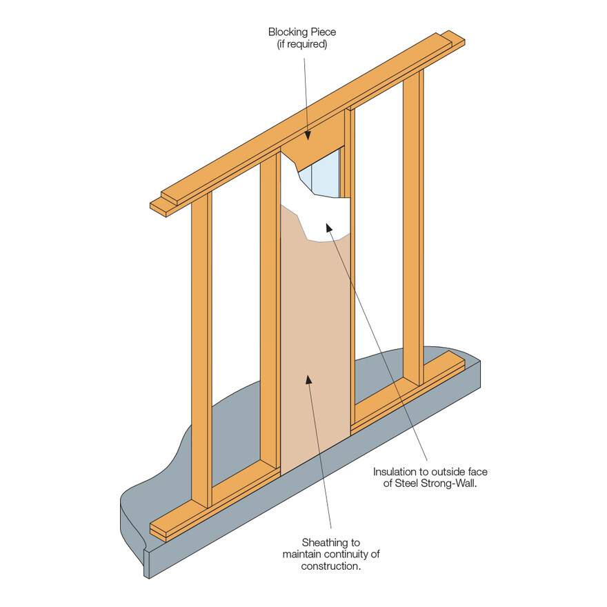
4c - Install insulation on the outer face of the Steel Strong-Wall panel and close off the panel by installing sheathing to the face of the timber studs - thus maintaining continuity in the timber frame construction.Sheathing to be installed with fasteners in accordance with engineers instructions.
