Image
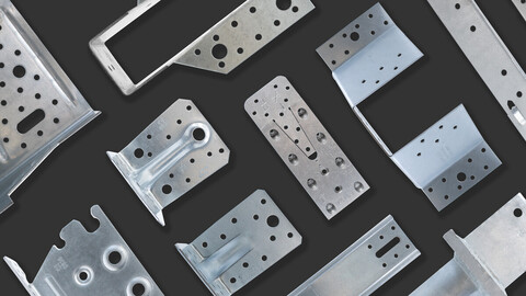
Reinforced angle brackets are suitable for structural applications in framing and wood-frame houses.









| Reference | Connector Dimensions | |||||||||||||
|---|---|---|---|---|---|---|---|---|---|---|---|---|---|---|
| Other | Product Dimensions[mm] | Joist[mm] | Flange B[mm] | |||||||||||
| Weight[kg] | A[mm] | B[mm] | C[mm] | Thickness[mm] | Round | Obround | Round | |||||||
| Ø5[mm] | Ø8.5[mm] | Ø11[mm] | Ø13 | Ø13x40 | Ø5[mm] | Ø8.5[mm] | Ø11[mm] | Ø13[mm] | ||||||
| ABR70 | 0.11 | 70 | 70 | 55 | 2 | 6 | 1 | - | - | - | 6 | 1 | - | - |
| ABR90 | 0.21 | 90 | 90 | 65 | 2.5 | 10 | - | 1 | - | - | 10 | - | 1 | - |
| ABR98 | 0.36 | 98 | 98 | 88 | 3 | 10 | - | - | 3 | - | 12 | - | - | 3 |
| ABR105 | 0.4 | 105 | 105 | 90 | 3 | 10 | - | 3 | - | - | 14 | - | 1 | - |
| Reference | Angle bracket capacity | |||||||||||||
|---|---|---|---|---|---|---|---|---|---|---|---|---|---|---|
| Product capacities - Timber to timber - Full nailing | ||||||||||||||
| Number of Fasteners | Characteristic Capacities - Timber C24 - 2 angle brackets per connection[kN] | |||||||||||||
| Joist | Flange B | R₁,ₖ | R2,k = R3,k | R4,k = R5,k(1) | ||||||||||
| Qty | Qty | CNA4.0x35 | CNA4.0x40 | CNA4.0x50 | CNA4.0x60 | CNA4.0x35 | CNA4.0x40 | CNA4.0x50 | CNA4.0x60 | CNA4.0x35 | CNA4.0x40 | CNA4.0x50 | CNA4.0x60 | |
| ABR70 | 4.0 | 6.0 | 4.38 | 5.34 | 7.11 | 8.89 | 4.55 | 5 | 6.89 | 7.33 | - | 3,0 / kmod^0,5 | - | - |
| ABR90 | 8.0 | 10.0 | 6.46 | 7.87 | 10.66 | 13.32 | 8.38 | 9.21 | 11.07 | 11.78 | - | 8,1 / kmod^0,85 | - | 9,1 / kmod^0,75 |
| ABR98 | 10.0 | 12.0 | 9.8 | 11.8 | 15.7 | 19.7 | 12.1 | 13.7 | 17.5 | 19.8 | 13.1 | 13.3 | 13.7 | 14 |
| ABR105 | 10.0 | 14.0 | 8.84 | 10.78 | 14.33 | 17.91 | 13.26 | 14.57 | 19.01 | 20.22 | - | 12,9 / kmod^0,5 | - | 14,5 / kmod^0,75 |
* b = 75 mm and e = 130 mm
To obtain the resistance values for a single bracket, the values in the above table should be divided by two, provided that the supported beam is locked in rotation. Please consult our ETA-06/0106 if the beam is free to rotate.
| Reference | Angle bracket capacity | |||||||||||
|---|---|---|---|---|---|---|---|---|---|---|---|---|
| Simplified product capacities - Timber to Concrete | ||||||||||||
| Number of Fasteners | Simplified characteristic capacities - Timber C24 - 2 angle brackets per connection[kN] | |||||||||||
| Joist | Flange B | R₁,ₖ | R2,k = R3,k | |||||||||
| Qty | Type | Qty | Type | CNA4.0x35 | CNA4.0x40 | CNA4.0x50 | CNA4.0x60 | CNA4.0x35 | CNA4.0x40 | CNA4.0x50 | CNA4.0x60 | |
| ABR105 | 10.0 | CNA | 1.0 | Ø10 | 4.08 | 4.88 | 6.48 | 8.08 | 2.25 | 2.68 | 3.55 | 4.37 |
*The published characteristic capacity is based on short term load duration and service class 2 according to EC5 (EN 1995) – kmod = 0.9. For other load duration and service class, please refer to the ETA to get more accurate capacities.
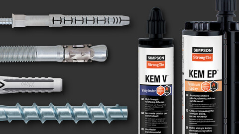
The bolt design resistance requirement R#,d is determined from (bolt factor x connection design load F#,d) for the required load direction and fastener. Refer to the Simpson Strong-Tie anchor product range for suitable anchors. Typical anchor solutions depend on the concrete type, spacing and edge distances.
To obtain the resistance values for a single bracket, the values in the above table should be divided by two, provided that the supported beam is locked in rotation. Please consult our ETA-06/0106 if the beam is free to rotate.