Microsites

Microsites

AG922

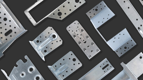
Large Reinforced Angle Bracket

Reinforced angle brackets are suitable for structural applications in framing and wood-frame houses.


CE Marking
CE Marking
ETA
ETA
Indoor
Indoor
Electrogalvanized steel Z275
Service class 2
Service class 2
EPD
EPD
Available in Connector Selector

Product Details

Images

Features

Material

  • Galvanized steel S250GD + Z275 according to NF EN 10346.

Advantages

  • High lateral capacity
  • High rigidity
  • Allow concrete header

Application

Header member

  • Supporting member: solid wood, glued-laminated wood, concrete, steel, etc.
  • Supported member: solid wood, composite lumber, glued-laminated wood, triangular trusses, profiles, etc.

Intended Use

  • Fastening of small trusses.
  • Cladding plates, cladding uprights.
  • Rafter anchors, cantilevers, headers, etc.

Technical Data

Product Dimensions

Dimensions

ReferenceConnector Dimensions
Product Dimensions[mm]Joist[mm]Flange B[mm]Other
A[mm]B[mm]C[mm]Thickness[mm]RoundRound Qty per BoxWeight[kg]
Ø5[mm]Ø13Ø5[mm]Ø13[mm]
AG922121791502.526218225.00.54

Wood/wood connection beam/beam type - assembly with 2 angle brackets

ReferenceAngle bracket capacity
Product capacities - Timber to timber - Beam to beam - Full nailing
Number of FastenersCharacteristic capacity - 2 angle brackets per connection - full nailing[kN]
JoistFlange BR₁.ₖR₂/₃.ₖ[kN]
QtyQtyCNA4.0x50CNA4.0x50
AG922161318.529.5

To obtain the resistance values for a single bracket, the values in the above table should be divided by two, provided that the supported beam is locked in rotation. Please consult our ETA-06/0106 if the beam is free to rotate.

Wood/wood connection post/beam type - assembly with 2 angle brackets

ReferenceAngle bracket capacity
Product capacities - Timber post to timber beam
Number of FastenersCharacteristic Capacities - Timber C24 - 2 angle brackets per connection[kN]
JoistFlange BR₁,ₖ
QtyQtyCNA4.0x50
AG92212.013.019.5

To obtain the resistance values for a single bracket, the values in the above table should be divided by two, provided that the supported beam is locked in rotation. Please consult our ETA-06/0106 if the beam is free to rotate.

Wood/rigid substrate connection beam/rigid substrate type - assembly with 2 angle brackets

ReferenceAngle bracket capacity
Product capacities - Timber beam to rigid support
Number of FastenersCharacteristic Capacities - Timber C24 - 2 angle brackets per connection[kN]
JoistFlange BR₁,ₖR2,k = R3,k
QtyTypeQtyTypeCNA4.0x50CNA4.0x50
AG92216.0CNA*2.0Ø1230.648.2

* Refer to Characteristic Capacity table columns for type of fasteners that can be used in Flange A. Capacities vary depending on fastener type used.

The bolt design resistance requirement R#,d is determined from (bolt factor x connection design load F#,d) for the required load direction and fastener. Refer to the Simpson Strong-Tie anchor product range for suitable anchors. Typical anchor solutions depend on the concrete type, spacing and edge distances.

To obtain the resistance values for a single bracket, the values in the above table should be divided by two, provided that the supported beam is locked in rotation. Please consult our ETA-06/0106 if the beam is free to rotate.

Wood/rigid substrate connection post/rigid substrate type - assembly with 2 angle brackets

ReferenceAngle bracket capacity
Product capacities - Timber post to rigid support
Number of FastenersCharacteristic Capacities - Timber C24 - 2 angle brackets per connection[kN]
JoistFlange BR₁,ₖ
QtyTypeQtyTypeCNA4.0x50
AG92212.0CNA*2.0Ø1237.5

* Refer to Characteristic Capacity table columns for type of fasteners that can be used in Flange A. Capacities vary depending on fastener type used.

The bolt design resistance requirement R#,d is determined from (bolt factor x connection design load F#,d) for the required load direction and fastener. Refer to the Simpson Strong-Tie anchor product range for suitable anchors. Typical anchor solutions depend on the concrete type, spacing and edge distances.

To obtain the resistance values for a single bracket, the values in the above table should be divided by two, provided that the supported beam is locked in rotation. Please consult our ETA-06/0106 if the beam is free to rotate.

Characteristic capacities - Beam/beam assembly - Connection with 1 bracket - F4

ReferenceAngle bracket capacity
Product capacities - Timber to timber
Number of FastenersCharacteristic capacities - Timber C24 - 1 angle brackets per connection[kN]
JoistFlange BR4,k
QtyQtyCNA4.0x50
AG92212.013.022.6

Characteristic capacities - Beam/rigid support - Connection with 1 bracket - F4

ReferenceAngle bracket capacity
Characteristic capacities - Timber to rigid support
Number of FastenersCharacteristic capacities - Timber C24 - 1 angle brackets per connection[kN]
JoistFlange BR4,k
QtyTypeQtyTypeCNA4.0x50
AG92212.0CNA*2.0Ø1224.8

Characteristic capacities - CLT beam to CLT beam - Ø12 connector screws - 2 angle brackets

ReferenceAngle bracket capacity
Product capacities - CLT beam to CLT beam - Ø12 connector screws - 2 angles brackets
Number of FastenersCharacteristic Capacities - Timber C24 - 2 angle brackets per connection[kN]
JoistFlange BR2,k = R3,kR₁,ₖ
QtyTypeQtyTypeSSH12x80SSH12x80
AG9222.0SSH2.0SSH2323

Installation

Installation

Fasteners

On wood:

  • CNA annular ring-shank nails dia. 4.0 x 35 or dia. 4.0 x 50 mm.
  • CSA screws dia. 5.0 x 35 mm or CSA screws dia. 5.0 x 40 mm.
  • Bolts.
  • LAG screws.

On concrete:
Concrete substrate

  • Mechanical anchor: WA M10-78/5 OR WA M12-104/5 pin.
  • Chemical anchor: AT-HP resin + LMAS M10-120/25 or LMAS M12-150/35 threaded rod.

Hollow masonry substrate:

  • Chemical anchor: AT-HP or POLY-GP resin + LMAS M12-150/35 threaded rod + SH M16-130 screen.

On steel:

  • Bolts.

Installation

  1. Come with the joist close to the header,
  2. Add nails/screws to fix the angle bracket to the joist,
  3. If timber header, the angle bracket is also fixed to the header with screws or nails
  4. If concrete header, attached the angle bracket using installation details from the anchor

Technical Notes

Technical information

F1: tensile force in the central axis of the angle-bracket
Particular situation of a fastening with only one angle-bracket:

  • If the overall structure prevents the rotation of the purlin or the post, the tensile strength is equal to half of the given value for two angle-brackets.
  • Otherwise, the connection resistance depends on the « f » distance between the vertical contact surface and the point of load application.

F2 and F3: shear lateral force
Particular situation of a connection with only one angle-bracket:

  • The resistance value to consider is equal to half of the one given for two angle-brackets.

F4 and F5: transversal force directed towards or opposite the angle-bracket

  • The connection resistance depends on the « e » distance between the base of the angle-bracket and the point of load application.
  • To consult corresponding loads, contact us.

Only F1, F2 and F3 forces for connections with 2 angle-brackets are present on this sheet.
For more information, contact us.

ZIP Packages

Buy Online

Contact

Simpson Strong-Tie U.K.

Simpson Strong-Tie

Cardinal Point, Winchester Road
Tamworth
Staffordshire
B78 3HG
United Kingdom